We'll take a small simulated image and rotate it. The image is called Model.fits. In this case we'll just make a second copy of Model.fits to get imag 2 and then we'll make up a TRS file that does the rotation about the center pixel in the image (X,Y=100,100).
We'll make our images for the command line: % cp Model.fits img1.fits % cp Model.fits img2.fits Here is our TRS file: 100.0 100.0 N 1.0 45.0 -100 -100 xofirt yofirst reflect fscal theta xolast yolast Since we want to convert img2, the name of our TRS file have to be: TRS.img2-XY2XY-img1 # to make thetransformation % clip_imshift_trs.sh img1.fits img2.fits NEW.fitsThe result of our experiment is shown below.
![]() |
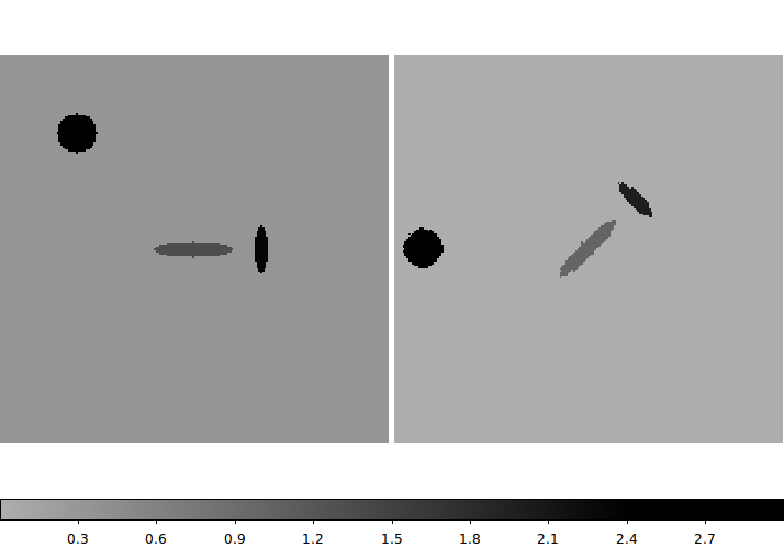
Our input image, Model.fits (img1.fits) is transformed using a TRS file:
Here is our TRS file: 100.0 100.0 N 1.0 45.0 -100 -100 xofirt yofirst reflect fscal theta xolast yolast % clip_imshift_trs.sh img1.fits img2.fits NEW.fitsThe oriniganl image (Model.fits) is on the left, and the transformed image (NEW.fits) is on the right. Our theta value of +45 degrees has caused the new image to be rotated 45deg in the counter-clockwise (CCW) direction. Becasue we subtracte 100,100 in the first translation, and then sadded 100,100 back in the second translation, the central ellipse remains in the center of the 200x200 test image. |