The fgstar routine, given a position in Ra,Dec coordinates, provides a view
of the IHMP (Input Head Mounting Plate) projeted on the sky. This is a Fast
vereion of an old code name gstar (Guide STAR), which was used primarily to locate
stars that could be used by the guide probes (gc1,gc2) or wavefornt sensors (wf1,wf2).
For a more detiled description see:
%  fgstar --help

Usage: fgstar 06:15:20.46 +39:51:50.6 304.0 gc1 N
arg1 - RA of IHMP center (sexigecimal)
arg2 - DEC of IHMP center (sexigecimal)
arg3 - Azimuth of HET structure (degrees)
arg4 - probe name (valid names = gc1,gc2,wf1,wf2)
arg5 - run in verbose/debug mode (Y/N)
Note that fgstar is a very old routine, and the argument parsing routines it uses
are very unsophisticated. In particular, the format of the sexigecimal Ra,Dec values
should match that shown above.
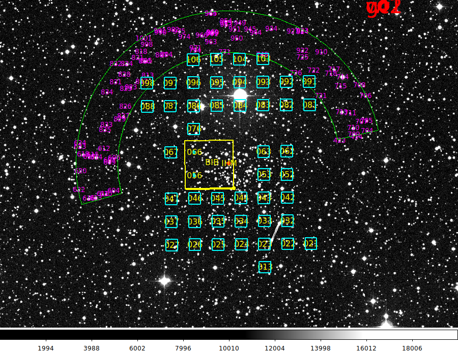
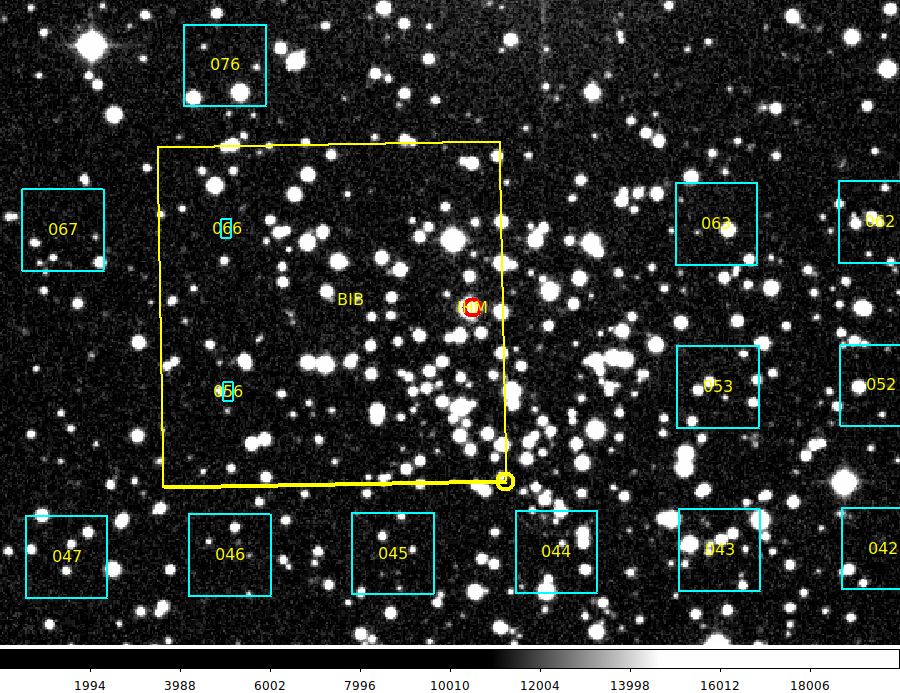
Below I show a typical example where I use a local file named "Faint_Mag.Limit" to set
the magnitude limit for stars plotted in the gc1 pickle to be 16.5 (in the USNO-B1.0
Red2 system). Note that had we not created this file a default value
of Red2=18.0 would have been used. Also, by creating the "No.Mark" file, I establish
that the routine will exit after the finding chart is created. Otherwise,
the user will be told to mark a circle region in the pickle. The (Ra,Dec) of
that circle region cenetr will then be written to a local file named "radec.gc1".
% ls
Faint_Mag.Limit
% cat Faint_Mag.Limit
16.5
% date > No.Mark
% fgstar 06:15:20.46 +39:51:50.6 304.0 gc1 N